Above is a " reverse engineered " rough layout of a circuit board by which we had to "trace out" and
derive a working electronic circuit layout to effectively service and repair a 30 output video amplifier
/ distribution box for our client to use and work from.
Someone had attempted (though very poorly) some 10 + years ago, to build a video duplication box with
30 outputs with using a now obsolete hex transistor array, which normally under digital or logic switching
would function as per the data sheet, however it was very much a different output when deployed as a
video amplifier, with odd stray parasitics due to the use of the same chip "die" within the LM3086N.
A bad choice of video amplification components by the previous designer of his version of a 30 way video
distribution amplifier.
Despite these problems, the owner "struggled-on" for years with a poor resolution output for his Tape
Duplication business. As there was no circuit available, we contacted the owner and explained that in
order to repair the unit, we would need to devise some form of workable schematic diagram, this was
before we discovered the stray "parasitics" and other inherent "noises" within each LM3086N chip.
The LM3086N is basically a six NPN transistor array in a 14 pin DIL package. It was good for other
types of switching such as controlling relays etc., however, in this application, absolutely not for good
video work.
Six T-05 "metal can" transistors would have been a far better choice and the tin can could be grounded.
This all takes time to carefully check for 100% accuracy and correct component orientation as well as
the correct data sheets and identification of each part. The circuit above took 2 hours to trace out and
a further 2.5 hours to carefully draw the relevant 100% accurate working electronic circuit.
Thus adding further costs to the client/customer's account.
While this method works fine for a single sided printed circuit board with parts on one side and copper
foil on the other, it becomes rather complex when there are two sides to the circuit board and parts
cover the track work. Impossible ? No,...Not always, however, with multilayer circuit boards, there
can be as few as three layers, top, bottom and middle. The middle could be a useful "RF" shield also.
Now comes a new entry into the mix. A multi-layer PCB with four, five and up to 32 layers in a single
manufactured PCB. That is virtually impossible to trace out using conventional methods.
A full schematic will help, however, unless you posses the schematics in full, complete with
all revision notes, you are wasting your time, and effectively our time also. Costly exercise. It's not on.
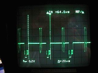
Note: The circuit (above) was "reasonable", however the "LM3086N chip transistor array" exhibited
thermally induced parasitics and a basic lack of performance, inherent picture instability, features
not conducive to a client's projected long term usage in a business where quality matters, in fact it
is an absolute requirement.
This more than likely resulted from aging stock and manufactured in circa 1994 and no longer made
by NS (National Semiconductor), So, after an in depth consultation with our client, it was resolved that
the unstable circuit boards were to be removed from the Video Duplication Box and returned
to our client, we set to and designed a fresh "new circuit" approach that was to adopted better outputs
thus providing our client with 50 good solid video outputs from one video input source. Our client was
highly delighted with our efforts and paid us accordingly. Times have changed since this was written.
VHS Video tapes have beed replaced by CDs then DVDs and BlueRay (all three names copyrighted).
The scrapped circuitry was fully removed and using the fresh new idea and approach, a viable circuit
design was skillfully produced, prototyped and tested by us at Unitech Electronics Pty. Ltd. and field
tested at the clients premises with all benefits measured in terms of reproduced picture quality on a
series of video tapes and the final test of a copy from a copy, this is the "acid test " on how well a copy
is being duplicated or made, the results were delightful, however, more importantly, our client was very
happy with our efforts and especially with the results. As a bonus from prototype testing, we were able
to include such benefits as 10 stage video signal attenuation to cater for various video input strengths.
Not all video tape signals are weak and not all are strong either. This attenuation worked very well.
Research and development on a project such as this takes time and money, more time and more
money usually, however, the end result is what counts, a very satisfied client, delighted with the
extra efforts and attention to detail we took to make sure each video output was fully stabilised and
that all 50 video outputs functioned correctly, thus providing an excellent amplified video signal Video
to all 50 outputs simultaneously to each and every VCR (VTR), with no distortion or color fate or drop
out, even with that extremely annoying Macrovision copy protection. The proof was in the copies.
Our client was able to continue with his Video production business, supplying his customers with
good quality videos at reasonable prices. Pride in our workmanship is why we are still around in 2019.
|